
















Angular Deflection
Viking Johnson couplings and flange adaptors will allow for a setting angularity (Ø) as shown in Table “Angular Deflection for Couplings and Flange Adaptor for Various Viking Johnson Products”
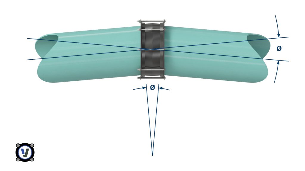
Angular Deflection for Couplings and Flange Adaptor for Various Viking Johnson Products
| Couplings | Flange Adaptors | |||
|---|---|---|---|---|
| Product | Pipe Size | Angular Deflection (Ø) | Minimum Closing Length L(mm) To Accommodate Displacement Y(mm) | Angular Deflection (Ø) |
| Flexible Products:- | ||||
| VJ Dedicated | DN350-450 | ± 6.0° | Displacement Y x 10 | ± 3.0° |
| VJ Dedicated | DN450-600 | ± 5.0° | Displacement Y x 12 | ± 2.5° |
| VJ Dedicated | DN600-750 | ± 4.0° | Displacement Y x 15 | ± 2.0° |
| VJ Dedicated | DN750-1200 | ± 3.0° | Displacement Y x 20 | ± 1.5° |
| VJ Dedicated | DN1200-DN1800 | ± 2.0° | Displacement Y x 30 | ± 1.0° |
| VJ Dedicated | DN1800 & Over | ± 1.0° | Displacement Y x 60 | ± 0.5° |
| QuickFit | DN50-300 | ± 6.0° | Displacement Y x 10 | ± 3.0° |
| MaxiFit | DN50-600 | ± 6.0° | Displacement Y x 10 | ± 3.0° |
| MaxiFitXtra | DN50-300 | ± 6.0° | Displacement Y x 10 | N/A |
| MegaFit | DN50-300 | ± 8.0° | Displacement Y x 15 | ± 4.0° |
| Restrained Products:- | ||||
| FlexLock | DN80-300 | ± 6.0° | Displacement Y x 10 | ± 3.0° |
| UltraGrip | DN50-600 | ± 8.0° | Displacement Y x 15 | ± 4.0° |
| Amplified UltraGrip | DN700-1200 | ± 8.0° | Displacement Y x 15 | ± 4.0° |
NOTES
- For flexible products, the above table represent the maximum angular deflection for each size range and should only be used when the pipes will not move in service. If further movement is predicted it is recommended to use halve these figures as maximum allowed at installation to allow for in-service flexibility.
- For restrained products, the above table represent the maximum angular deflection for each size range and once installed no further deflection in service is possible.
The ability of Viking Johnson couplings to accommodate angular deflection, either on installation or in service, can be used in several valuable ways:
- To take up minor misalignment or lateral displacement in straight pipes, e.g. at closing lengths, or in repair situations with congested pipe trenches.
- To accommodate ground settlement.
- To lay pipes to long radius curves without special bends.
Lateral Displacement
Lateral displacement between two pipes can be easily accommodated using two couplings and an appropriate length of closing pipe which can be allowed to angulate. The length, L(mm), of the closing pipe can be calculated from Table “Angular Deflection for Couplings and Flange Adaptor for Various Viking Johnson Products” by multiplying the displacement Y(mm) by the figure noted.
NOTE: A single coupling cannot accommodate lateral displacement
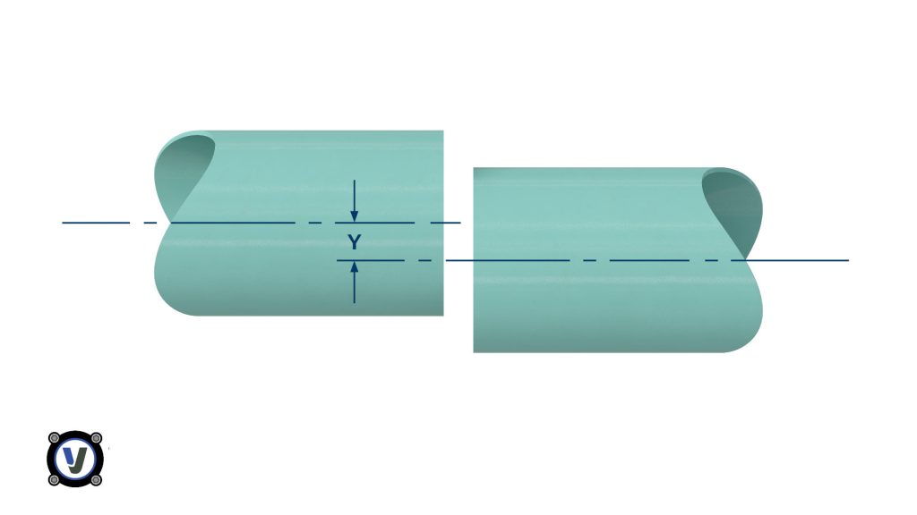
Lateral displacement (Y) can be accommodated using two couplings
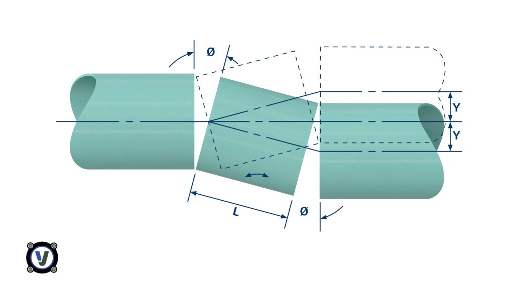
Length of closing pipe (L) depends on maximum angularity (Ø).
Ground Settlement
Ground settlement, for example where a pipe leaves an underground structure, may be accommodated using a pair of Viking Johnson couplings. In this case, pipe trenches are excavated below the pipe invert to allow for pipe bedding. If this bedding is flexible (e.g. granular fill), some settlement will inevitably occur when the trench is backfilled.
Ground Settlement. Displacement Y can be accommodated using two couplings A & B and a rocker pipe length L:
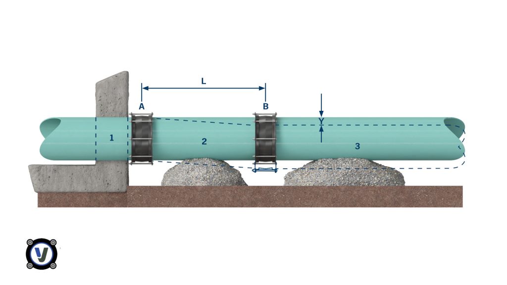
To minimise stresses in pipe 1, coupling A should be installed as close as possible to the structure. The two couplings A and B allow pipe 2 to angulate to take up settlement Y. The minimum length L of pipe 2 is determined from Table “Angular Deflection for Couplings and Flange Adaptor for Various Viking Johnson Products”. The structural strength of the pipe in bending may need to be considered.
Alternatively, a Viking Johnson wall coupling can be used instead of pipe 1 and coupling A.
Long Radius Curves
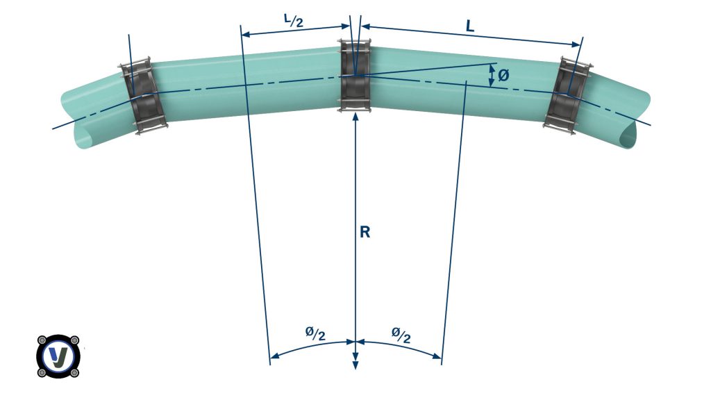
Using the angularity capability of Viking Johnson couplings makes it is possible to lay a pipeline with long radius curves, taking a small change in direction at each coupling, without the need for special large-angle bends with associated thrust blocks. This method can be used to avoid major obstacles on cross-country pipelines or follow the line of roads or streams, etc. using the equation given below.
Where L = pipe length
ø = angular deflection
r = radius of curve
Long radius curves can be accommodated without special bends:
NOTE: In an above ground pipeline, lateral pressure thrusts will need to be restrained by the support system. Buried pipes laid to a curve will normally receive sufficient support from the trench backfill material.